If you found this page searching for 3d ai studio, this guide is about the step after generation: turning an AI-made mesh into a PrusaSlicer-ready model. It covers inspection, repair, orientation, supports, color, and cuts without changing the article’s original workflow.
The work between generating a model and slicing it is mostly inspection: checking the invented surfaces, choosing a useful orientation, and making sure fragile details will print. Here is the photo-to-PrusaSlicer workflow I use, including what changes when a model needs supports, color, or a cut.
The short version
- Start with a clear picture of one subject, preferably from a three-quarter view. Check the generated back and underside; the AI has to invent anything the picture does not show.
- Repair the mesh and export STL for a single-color print, or 3MF when you want the model in a project file. Expect to repaint color in PrusaSlicer.
- In PrusaSlicer, set the intended height, find a stable orientation, and inspect the sliced preview for missing thin features and unsupported overhangs.
- Use organic supports where the shape needs them, put finer layers on visible curves, and keep the seam away from the face.
Step 1: Give the generator a shape it can read
PrusaSlicer prepares an existing mesh; it does not create a model from a photo. SupaVoxel’s Prusa 3D models workflow handles that earlier step, turning a picture into geometry you can then prepare in PrusaSlicer.
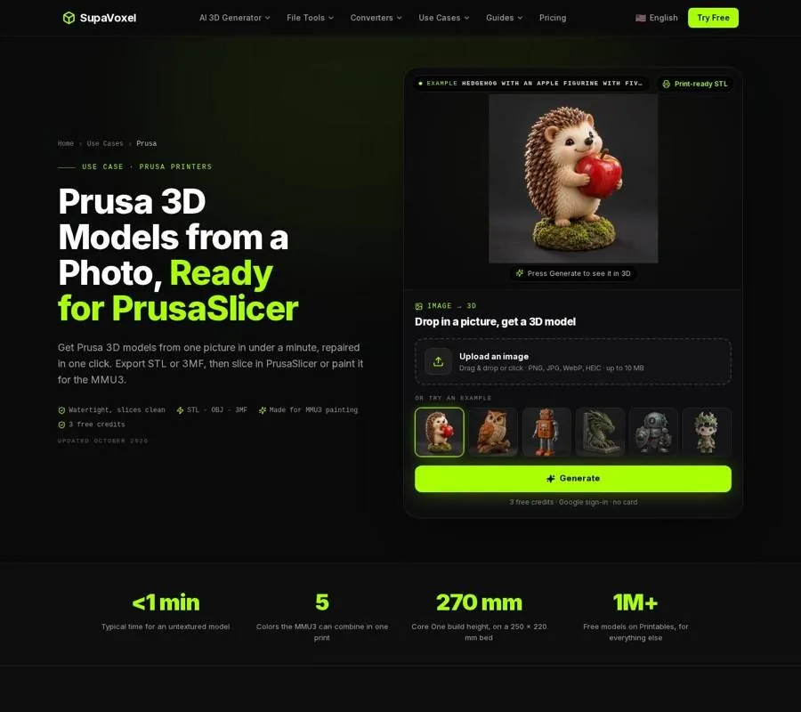
The Prusa page shows the photo-to-mesh step that comes before slicing.
Choose a photo in which the subject fills most of the frame. A three-quarter view gives the generator more information about depth than a straight-on portrait, while soft light makes the outline easier to distinguish from dark shadows. Keep it to one subject. A group photo asks the generator to guess where one body ends and another begins.
The page accepts PNG, JPG, WebP, and HEIC files up to 10 MB. It removes the background, and you can supply up to 4 additional angles. Use those angles when the back, tail, handle, or other important feature is unclear in the main image. More views cannot rescue a feature that is hidden in every picture, but they can reduce the amount of geometry the AI must invent.
Think about the eventual print while choosing the image. A compact pose is easier to orient and support than one with arms reaching far from the body. Fine hair strands or whiskers may look convincing on screen but fail to survive printing through a 0.4 mm nozzle. If those details define the subject, plan to represent them as thicker, joined shapes rather than expecting the photographed detail to transfer literally.
Step 2: Inspect the mesh, not just the familiar view
Once generation finishes, rotate the model all the way around. Look first at the sides the photo did not show, then tilt it to inspect the underside. The front can resemble your reference while the back contains an unwanted bulge or a limb merges into the torso. Those are shape decisions, not slicer settings; supports will not correct them.
I also look for the surfaces that could touch the build plate. A broad, fairly flat area makes orientation simpler. If the subject has no suitable base, decide which surface can tolerate support marks before exporting. The best-looking front view is not necessarily the best printing orientation.
Check thin projections separately: ears, fingers, tails, and similar features may be present in the mesh yet disappear in the sliced preview. Scaling the whole model up can make them printable, but it also changes the finished size. Make that trade-off deliberately rather than discovering it after printing.
An untextured generation is usually ready in under a minute; a textured one typically takes 3 to 5 minutes. That is only the mesh-generation stage. Leave time for inspection and for the ordinary slicing decisions that follow.
Step 3: Repair and choose the export
For printing, the mesh needs to describe a solid with a clear inside and outside. A hole, disconnected surface, or reversed face can make that ambiguous. “Watertight” means the surface closes around the volume; it does not mean every small feature is strong enough to print.
Use the workflow’s repair step before export. Its in-studio repair and other generated-model print-prep features are included in every paid plan from $25 a year. Then choose the file for the job: STL is the straightforward single-color choice, while 3MF keeps the model in one project file. Direct STL and 3MF downloads require a paid plan; new accounts receive 3 free credits at sign-up for generation.
Do not treat the exported size as the intended print size. AI models can arrive at an arbitrary scale, and STL itself does not define physical units. Set the height you actually want after importing the geometry into PrusaSlicer. This is also why I avoid making fit or strength decisions from the generator’s preview alone: the final dimensions matter.
If you intend to print with an MMU3, keep the geometry and its color workflow separate in your mind. SupaVoxel’s multi-color 3MF uses a triangle-paint format read by Bambu Studio and OrcaSlicer. PrusaSlicer handles painted colors differently, so import the geometry and plan to paint the color regions again there.
Step 4: Set scale and orientation in PrusaSlicer
Drag the export onto the plate and set its height in millimeters with the scale lock on. Keeping the proportions locked matters for a recognizable figure: changing just one axis may make a face or body look wrong even if the model still slices.
Next, rotate the model until its most useful flat area rests on the sheet. The aim is not simply to minimize supports. You also want a stable contact area, sensible layer direction for thin features, and support contact on surfaces that will be less visible. A small orientation change can move support marks from a face to the back or put an overhanging hand within reach of supports rising from the plate.
Use the stock profile for your printer and filament as the starting point. Then slice once and inspect the preview. Follow the layers through the thin parts rather than judging only the solid model view. If an ear or finger vanishes, try a larger scale or reconsider whether the feature needs a thicker source shape. If an island appears before anything underneath can hold it, revisit orientation or support placement.
The preview is the handoff between “this looks like the photo” and “this can be built in layers.” I would not send an AI-made figure to the printer without checking both.
Step 5: Place supports, detail, seams, and color
Organic supports are a useful starting point for arms, chins, and other overhangs. Start with supports from the build plate, then check the preview for areas that still need help. Paint support blockers on a visible face if branches would scar it; enforce support under a hand or chin if that area would otherwise begin unsupported. The goal is enough contact to print the feature without treating every visible surface as a support target.
For a figure with curved upper surfaces, use PrusaSlicer’s adaptive variable layer height and smooth the result. Finer layers help on rounded heads and faces, while less visible or straighter regions need not receive the same treatment. Inspect the layer preview again after changing it: surface detail and support decisions should make sense together.
The seam deserves its own pass. On a round figure, an exposed seam can draw the eye even when the rest of the surface prints cleanly. Align it toward the back or paint its position onto a less visible region. Rotate the sliced preview, not just the model, to see where it lands.
For an MMU3 print, PrusaSlicer’s multi-material painting tool lets you assign the regions after import. The MMU3 can combine up to 5 filaments in a print. Favor broad, readable color areas over tiny scattered patches; each isolated patch adds color changes, and a photo’s texture need not become a separate filament color.
When the model needs a cut or a mold instead
A model can be printable in principle yet awkward as one piece. A tall figure may exceed the build volume, or a bust may demand supports across its most important surface. In that case, a cut can make the next steps easier. SupaVoxel’s free STL splitter cuts a model into closed parts with flat faces and optional alignment pins.
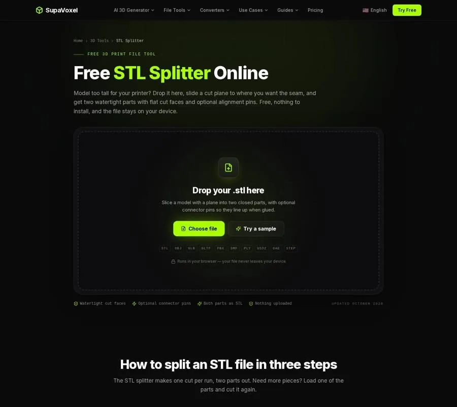
The splitter page shows the cut-plane workflow and the resulting parts.
Put the cut where a seam belongs visually, such as beneath a collar or at a waist, rather than through a narrow wrist. The tool offers horizontal, left-to-right, and front-to-back cuts. Check that both results are marked closed, then keep their scale identical in PrusaSlicer so the pins and holes still match.
A different decision arises if the print is only a master for casting. SupaVoxel’s free STL mold maker creates a printable block mold with two halves, alignment keys, and a pour hole. That is not a substitute for splitting an oversized display print. It is a separate route for making cast copies, and the subject must be able to release from a rigid mold without undercuts trapping it.
FAQ
Does PrusaSlicer generate a model from my photo?
No. Generate the mesh first, then bring its STL or 3MF into PrusaSlicer for scale, orientation, supports, painting, and slicing.
Will a multi-color 3MF arrive with its colors ready for the MMU3?
Not reliably. PrusaSlicer uses a different painted-color format from the one in SupaVoxel’s multi-color 3MF. Import the geometry and repaint the regions with PrusaSlicer’s multi-material tool.
Why did a feature disappear even though I could see it on the model?
The feature may be too thin at your chosen print scale. Inspect the sliced layers, try scaling the model up, and check that overhanging features have support. A closed mesh solves surface errors; it cannot make a feature wide enough for the nozzle.